
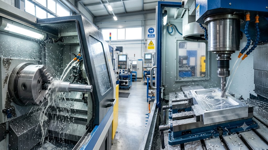
If you are sourcing precision machined components, one of the first questions a good machine shop will ask is: does this part turn or does it mill? It sounds like a simple question, but the answer determines which machines run your job, how many setups are required, what the achievable tolerances are, and ultimately what the part costs.
This guide explains the difference between CNC turning and CNC milling, how to identify which process your part calls for, and what to do when the answer is both.
What Is CNC Turning?
Turning is performed on CNC lathes and Swiss CNC machines. Swiss turning — which uses a guide bushing at the cutting zone to support the workpiece – is particularly suited for long, slender, small-diameter parts that would deflect on a conventional lathe. Modern turning centers also include live tooling: driven rotary tools mounted on the turret that allow milling, drilling, and tapping operations within the turning cycle.
Rule of Thumb
If your part is primarily round or cylindrical – a shaft, bushing, fitting, fastener, pin, or spool – it belongs on a turning machine.
What Is CNC Milling?
CNC milling is a machining process in which the workpiece is stationary and a rotating multi-flute cutting tool removes material by moving across the workpiece surface. The cutter moves in X, Y, and Z to produce flat faces, pockets, profiles, slots, holes, and contoured surfaces.
Milling is performed on vertical machining centers (VMCs) and horizontal machining centers (HMCs). Vertical milling centers are the most common configuration for prismatic parts – brackets, plates, housings, and flanges. Horizontal machining centers with rotary tables handle heavy workpieces and multi-face machining – castings, forgings, and large manifolds.
Advanced configurations add rotational axes: 4-axis milling adds indexing or continuous rotation around one linear axis; 5-axis milling adds a second rotational axis, enabling compound-angle features and complex surface profiles.
Rule of Thumb
If your part is primarily flat, prismatic, or requires machining on multiple faces – a bracket, housing, plate, or manifold – it belongs on a milling machine.
The Decision Framework: Turning vs Milling
The geometry of your part determines the process. Here is how to think through it:
| Part Characteristic | Turning | Milling |
|---|---|---|
| Primary shape | Round, cylindrical, or symmetrical about a center axis | Prismatic, flat, or multi-face geometry |
| Primary features | OD/ID diameters, threads, grooves, chamfers, bores | Flat faces, pockets, slots, profiles, contoured surfaces |
| Input material form | Bar stock (round, hex, square) | Billet plate or near-net castings and forgings |
| Ideal examples | Shafts, bushings, fittings, fasteners, spools, pins | Brackets, housings, plates, manifolds, flanges |
| Cost efficiency at volume | Very high — bar-fed automation, minimal setup | Moderate — depends on part complexity and setup time |
Live Tooling: When Turning Needs Milling Features
Many turned parts require features that a pure turning operation cannot produce – a cross-drilled port, a milled flat for a wrench, a keyway, or a tapped radial hole. Adding a separate milling operation used to mean a second setup, a second machine, and accumulated error between the two operations.
Modern CNC lathes with live tooling eliminate this problem. Driven rotary tools in the turret perform milling, drilling, and tapping operations within the turning cycle. The part never leaves the chuck – all features are machined from a single datum in a single cycle. The result is better accuracy, shorter lead time, and lower cost than routing the part through a separate milling machine.
Mill-Turn Centers: When One Machine Does Both
For the most complex parts, 9-axis mill/turn centers combine full CNC turning with simultaneous multi-axis milling in one machine. The same cycle that turns the OD and bores the ID also cross-drills ports, mills flats, threads ends, and completes back-face operations on the sub-spindle – all in one uninterrupted program.
The accuracy advantage of single-setup machining is substantial. Each time a part moves between setups, re-fixturing introduces positional error – typically 0.002″ to 0.005″ – that accumulates across features. A part completed on a mill/turn center has all features referenced to a single datum, holding positional tolerances between turned and milled features that separate operations simply cannot achieve reliably.
Practical Examples
Example 1: Hydraulic Spool Valve
A hydraulic spool valve is a long, slender cylinder with close-tolerance OD, cross-drilled metering ports, and milled flats. This is a turning job – specifically a Swiss CNC job. The OD is turned to close tolerance, the ports are cross-drilled with live tooling, and the flats are milled – all in one Swiss cycle.
Example 2: Manifold Block
A hydraulic manifold block is a rectangular aluminum or steel billet with multiple drilled and tapped ports on several faces, intersecting internal passages, and precisely located port positions. This is a milling job – specifically horizontal milling with 4th-axis indexing to machine all four port faces without re-fixturing.
Example 3: Custom Shaft With Keyway and Threaded Ends
A custom shaft requires turned OD steps for bearing seats, a milled keyway, threaded ends, and a cross-drilled hole. This is a mill/turn job – all features completed in one Y-axis dual spindle cycle for maximum accuracy between bearing seat concentricity, keyway angular position, and thread axis alignment.
Cost Implications of Choosing the Right Process
Choosing the wrong process costs money in two ways. First, it increases cycle time — a round part on a milling machine requires more setups and longer total machine time than the same part on a lathe. Second, it reduces accuracy — features machined in multiple setups accumulate re-fixturing error that a single-setup process avoids.
When you send a drawing to Resolute Precision, we assess the geometry and recommend the right process — turning, milling, or mill/turn — before we quote. Our goal is the shortest cycle, the best accuracy, and the lowest per-part cost for your specific geometry.
Summary
The turning vs milling decision is driven by geometry, not preference. Round symmetrical parts belong on turning centers. Prismatic multi-face parts belong on milling centers. Parts that require both benefit from live tooling lathes or mill/turn centers that eliminate secondary operations and deliver better accuracy at lower cost.
When you are unsure which process your part calls for, send us the drawing. We will tell you exactly which machine will run it and why.
Have a Part to Quote?
Send us a drawing. We will have a manufacturing feasibility note and real price back to you within 24 hours. No commitment, no pressure – just a straight answer from the people who will run your job. Contact Us or call (260) 665-6463.